


LEGO Architecture meets BIM – Part 15: Quality Assurance
Introduction
Model authors do their best to ensure that models are accurate but it is inevitable that even the most diligent of individuals will miss items that will cause issues for themselves or others. It is therefore imperative that information is checked. Information can be checked manually of course and there is always a place for manual checking. However software tools now allow model checking to be carried out in an automated way.
Checking of models can be split into 2 main areas – geometry and data.
Geometry Checking
Geometry checks are often referred to as “clash detection” but geometry issues can be far more than two pieces of geometry overlapping with each other. For example a pipe may not clash with anything but it may impede a door being opened or maybe visually not required behind a glazed element. These types of geometry issues can also be detected with a rule based approach. All of these issues can be referred to as coordination. Coordination management is the responsibility of the Design Lead, typically the Architect (see Figure 10 of PAS 1192-2:2013). This coordination exercise has always existed, the only difference with BIM is the model and associated checking tools allow this process to be more efficient and more reliable. In fact, I would suggest that we are coming close to charging more for coordinating 2D information compared to 3D models as it takes longer and still has the potential to not be fully coordinated.
Another geometry check that may be relevant is to review the Level of Detail (LOD) in a model. We covered Level of Detail in an earlier post. At the moment this check is largely a manual visual check but rules can be inserted into the rule based checking that are manual rules that need to be approved by the individual checking the model.
Data Checking
Data checking is a little more complex and can be further split into two areas: Validation and Verification.
- Validation is an automatic computer check to ensure that the data entered is sensible and reasonable. It does not check the accuracy of data.
- Verification on the other hand is performed to ensure that the data entered exactly matches the required value.
In my view Verification must be the responsibility of the information originator, unless the client has specified an exact value that can be compared against (e.g. Project Name, Site Name, Building Name provided in an Employer’s Information Requirements (EIR) document).
An Information Manager can only really carry out Validation (except where required values are known) and this is particularly important where information is federated to create a single output (i.e. COBie).
It is important to understand the difference between Validation and Verification when clarifying the quality of the model (or any information). With data it is inevitable that some manual checking is required but as we have seen in an earlier post it is possible to visualise data in a 3D model and this can be used as part of a Validation process.
Model Checking Process
You probably thought the LEGO model is perfect. The reality is it isn’t! (this was of course deliberate for the purposes of the blog series).
So for the LEGO model we created some rules just to demonstrate the model checking process. Our model checking is carried out with Solibri Model Checker but other tools are of course available. Some tools focus solely on geometry issues and others on information issues. Solibri covers both. We have primarily focussed on geometry checks to show issues as we wanted the data to be accurate for other purposes.
We have built a standard set of rules for architectural projects, although we have now further developed these for checking other discipline models and also add client specific rule based checking where required.
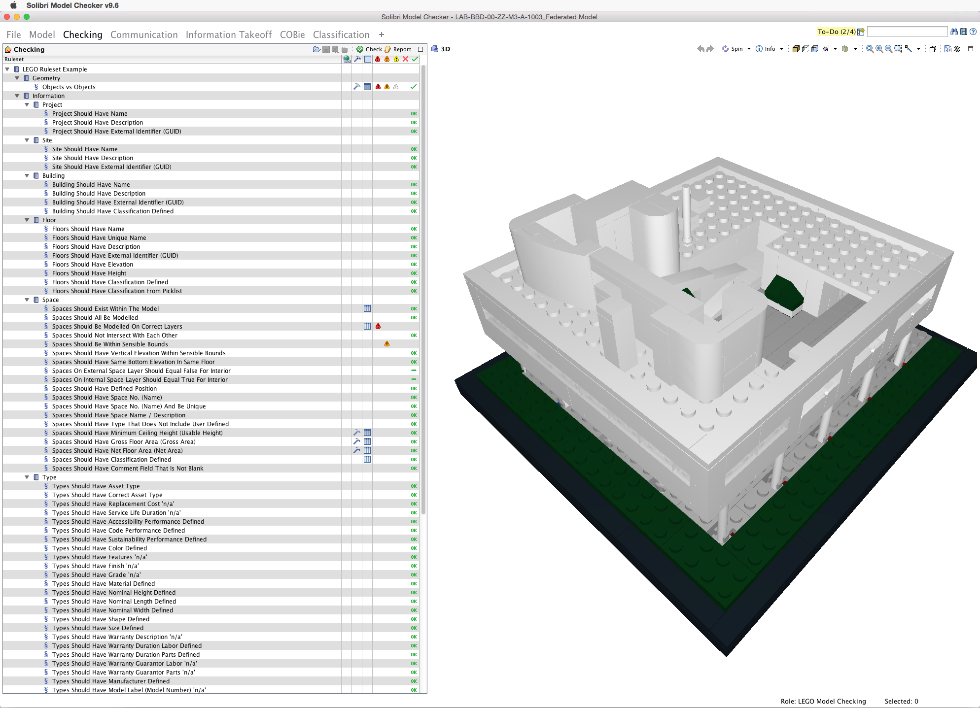
So below is how the checking looks once the rules have been run. Where the rule is passed the rule will say ‘OK’ next to it. Rules that fail are graded in severity. It is important to note that because a rule has failed it does not mean that this will be an issue on site. Solibri allows these rules to be manually approved and once they are a ‘tick’ will appear. This will show it has been passed but only with manual intervention.
Image: Checking is run against the model with results on the left
Below is an example of one of the geometry issues that Solibri Model Checker raised. This would not have been spotted manually by simply looking at the 3D model as it was not clearly visible when spinning around the model. This issue clearly should be resolved if we wanted to build this as the components won’t work on ‘site’.
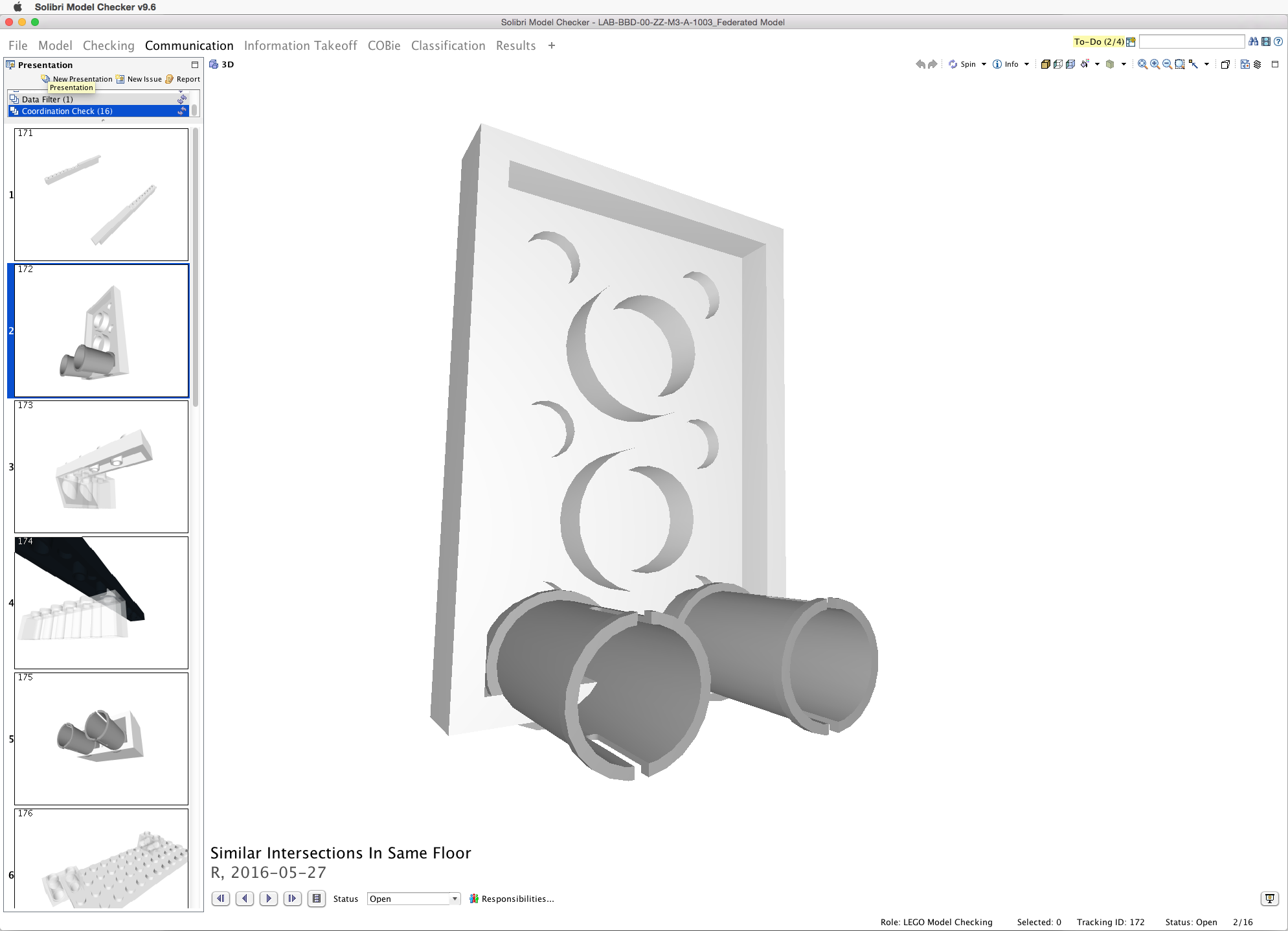
Image: An example of an issue picked up by the model checking
The model checking process revealed 16 “major” issues (very minor issues have been ignored for the purposes of explaining this process) which are shown below. Even some of these issues are pretty minor but they demonstrate how we can see each issue in isolation of the model with the relevant components that are issues shown in the 3D space.
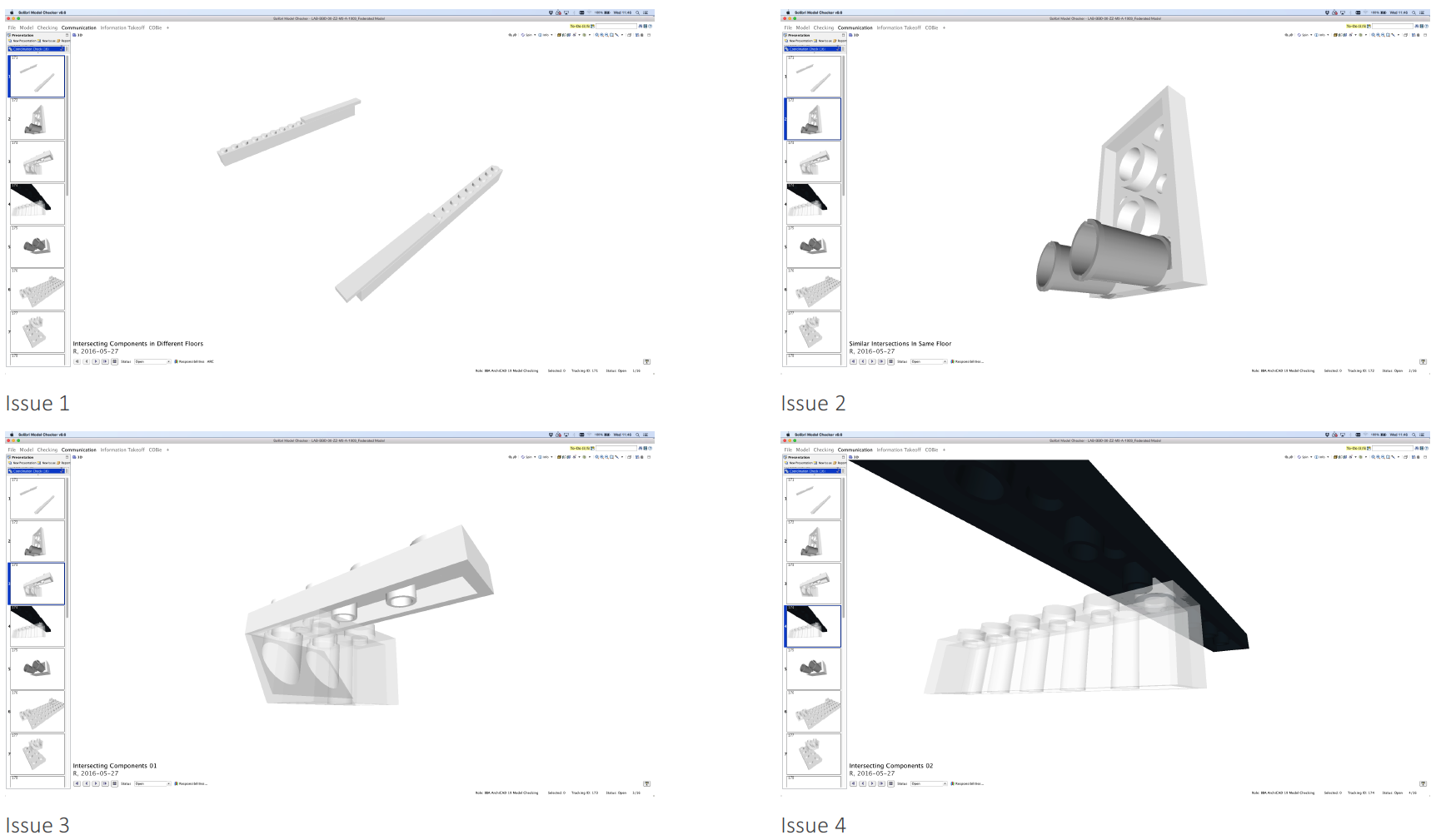
Image: Model issues 1-4

Image: Model issues 5-8
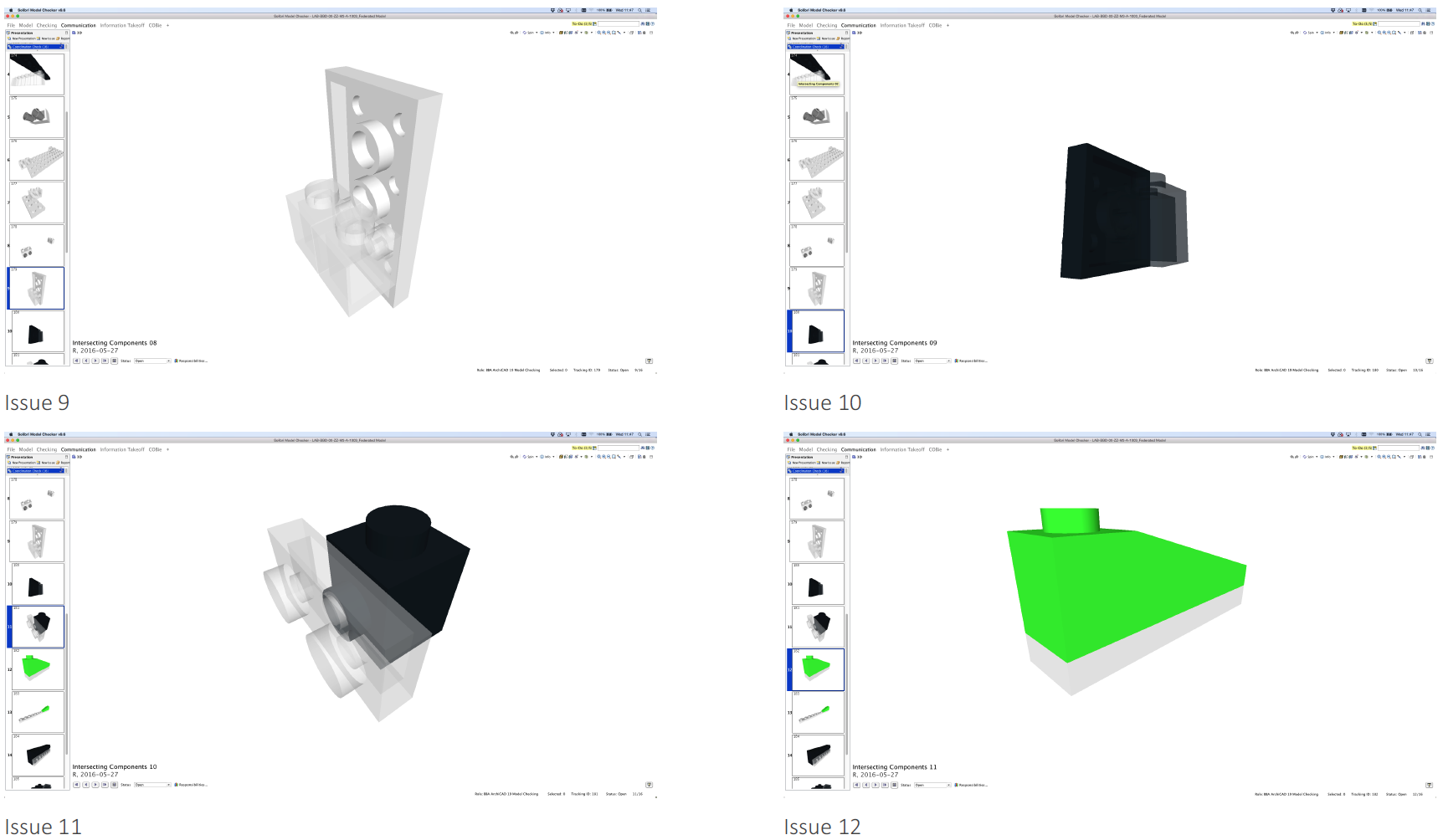
Image: Model issues 9-12

Image: Model issues 13-16
Reporting
Once we have identified the issues we have a number of ways of communicating the issues to others. This can be done by sharing the Solibri Model Checker file. This will be a file with an .SMC extension. The file can be opened by others in Solibri Model Viewer for free on both Mac and PC.
Alternatively we can create a PDF or Excel report. Below is an example of an Excel output from Solibri.
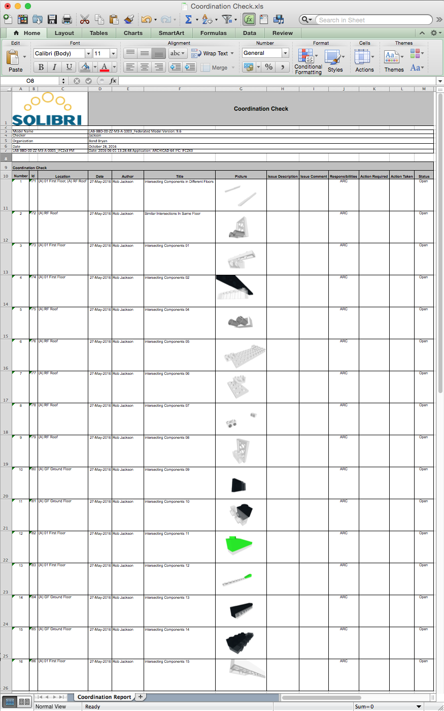
Image: The 16 identified issues documented in Excel
The final method is to create a BCF file. BCF stands for BIM Collaboration Format (an acronym within an acronym!). A BCF file allows the issues to be sent directly back to the original authoring tool. A BCF file takes the author directly to the issue in their model allowing them to resolve the identified issue quickly.
We will look in the next post how we can use the BCF file further.
Conclusion
Checking of models and rectification of issues is critical where the model needs to be used for another purpose. Today most focus is still on checking geometry but data needs to be checked if you want to use the model for other processes such as quantity take-off or for exchanging data into facilities management tools.
Some think that a model can be “clash free” and that focusing on the number of issues left to solve helps understand the quality of the model. However, the process of checking is about removing real issues that will cause others an issue. If you hope to achieve a 100% perfect geometry as it would be in the real world you will probably never finish the project! The main aim is to focus on the biggest issues first and slowly eradicate smaller and smaller issues during the design process.
Identifying issues though is only the first step in the quality process. Some of the issues raised by the tools may not be real issues that need action and those that are will need to be managed in order to eliminate the issues. In the next post we will look at how we can manage these issues effectively.
Rob Jackson, Associate Director, Bond Bryan Digital
![]()
Terms and conditions
All content provided on this BIM Blog is for informational purposes only. The owner of this blog makes no representations as to the accuracy or completeness of any information on this site or found by following any link on this site. Bond Bryan will not be liable for any errors or omissions in this information nor for the availability of this information. Bond Bryan will not be liable for any losses, injuries, or damages from the display or use of this information.
We are happy for others to share our blog pieces through all social media platforms. You may include links to the original blog pieces and use part of the blog to then provide a link to the original content. However we would appreciate it if the content is not reproduced in full on other sites or publications without written consent being granted by Bond Bryan.
This policy is subject to change at any time.
LEGO and the Lego logo are trademarks of the LEGO Group. Any trademarks, service marks, product names, corporate names or named features are assumed to be the property of their respective owners, and are used only for reference, without intent to infringe.