


LEGO Architecture meets BIM – Part 02: Model views
Introduction
In the previous blog post we showed images of the 3D model we have created of the Villa Savoye from the Lego Architecture series. A 3D model is easy for all parties to understand what the proposed model will look like once ‘built’. However the industry still requires designers to produce ‘traditional’ information including plans, sections and elevations on drawing sheets.
In order to create drawing outputs we must first create ‘views’ of the model. This post shows some of these views that can be created from the example 3D model.
All of the following views have been extracted directly from the 3D model. No 2D information has been applied to these views. This includes the level information shown in the Elevation and Section views which are generated automatically from the model.
At this stage these are simply views in the authoring tool, in this case Graphisoft ARCHICAD. Authoring tools allow different views to be created based on a variety of settings. Tools vary slightly in terms of views that can be created but all BIM authoring tools can produce plans, sections and elevations.
Plans
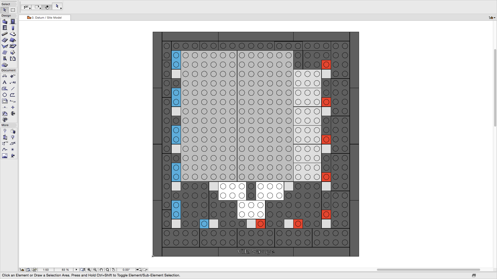
Plans are a horizontal cut of the model looking vertically down at the information in the model. The model can be cut at any height and typically these are cut for each floor level. Sometimes it is necessary to create multiple views of the same level to display different information.
Image: Site plan view (click to enlarge)
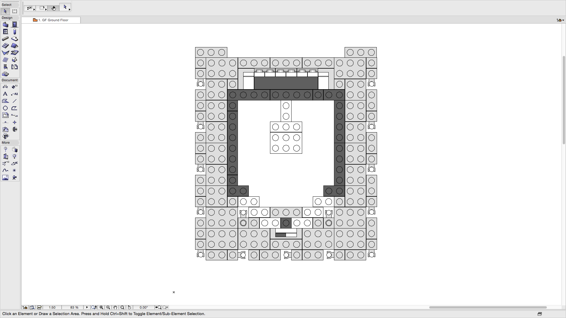
Image: Ground floor plan view (click to enlarge)
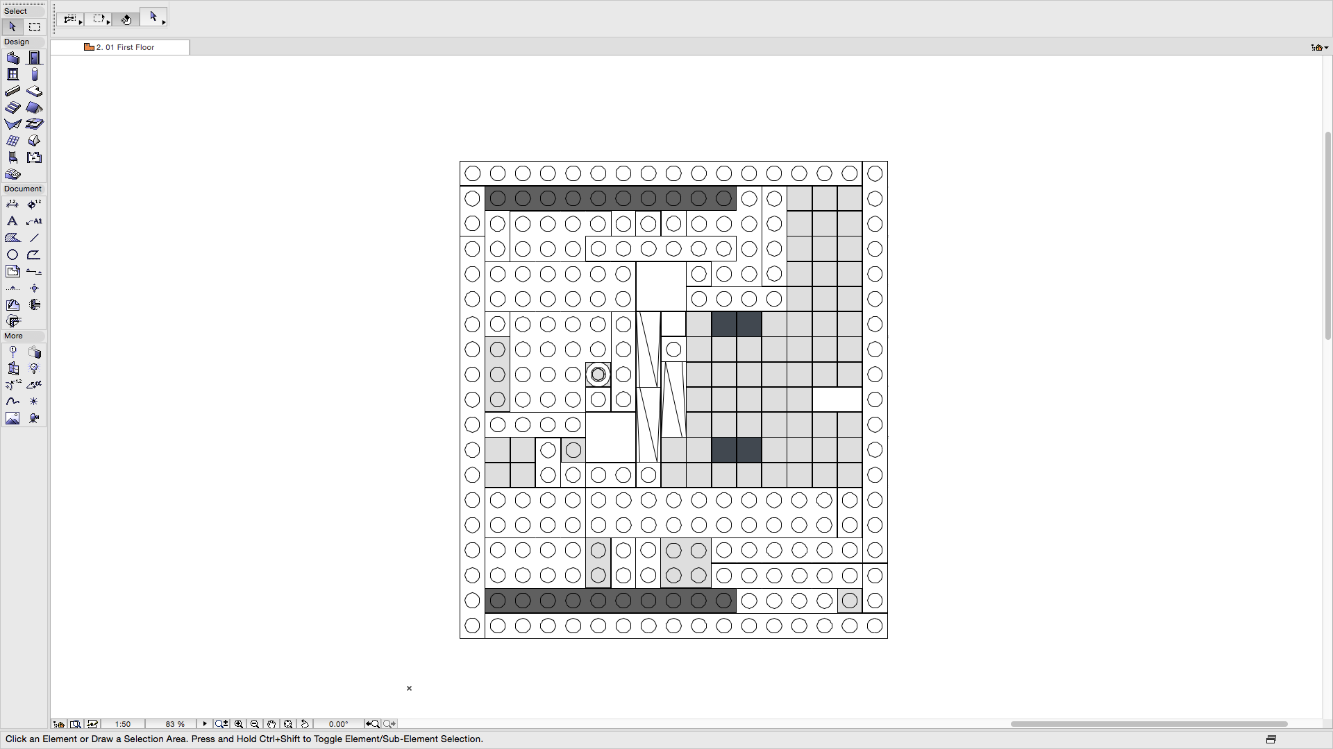
Image: First floor plan view (click to enlarge)
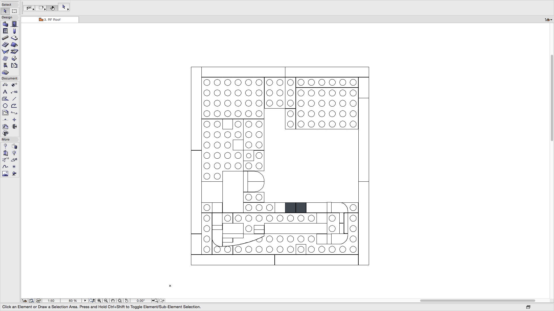
Image: Roof plan view (click to enlarge)
Elevations
The following are the four primary elevations of the model. Elevations are vertical views of the model, typically taken to show each side of the building.

Image: Elevation view 1 (click to enlarge)
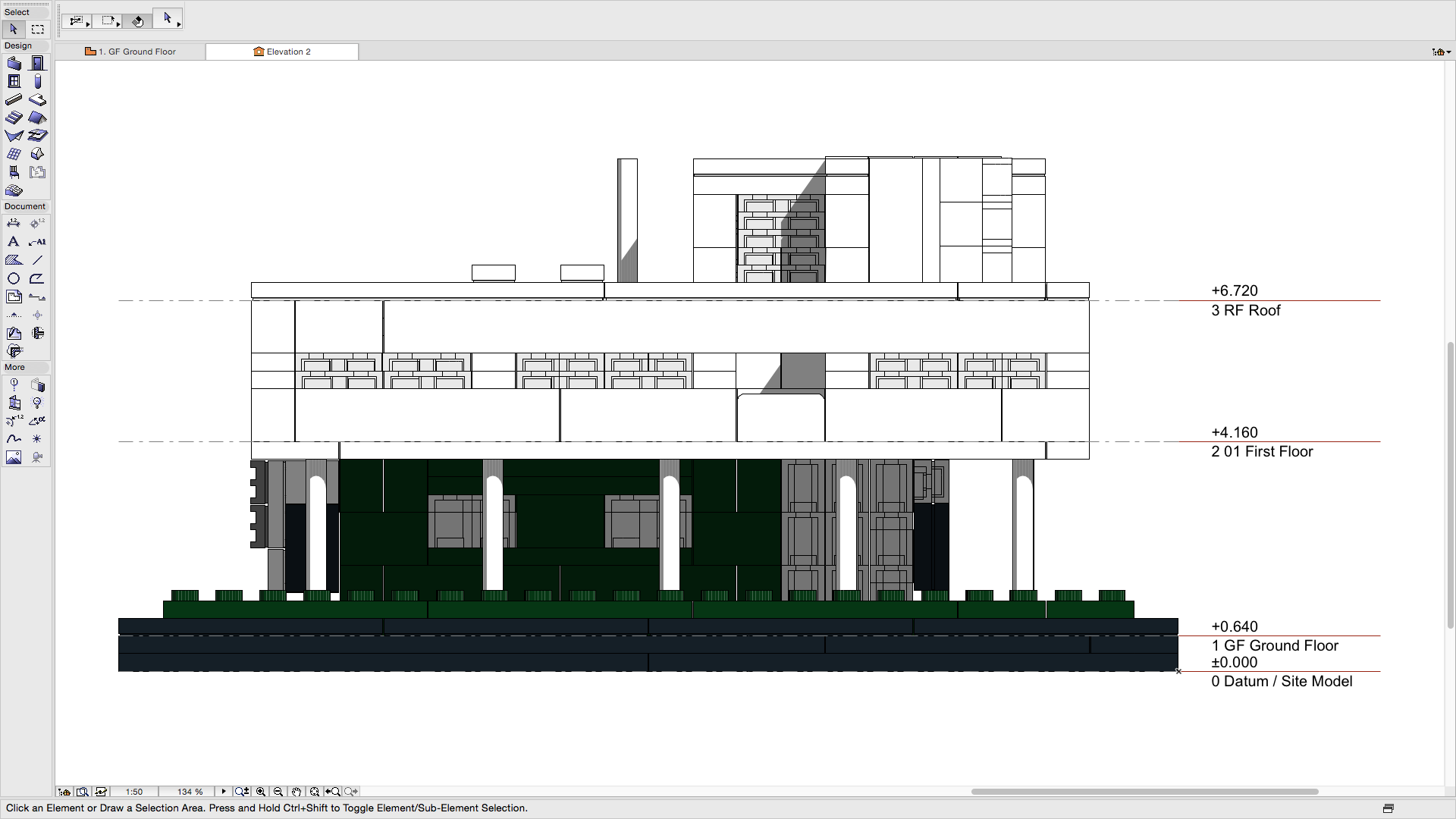
Image: Elevation view 2 (click to enlarge)
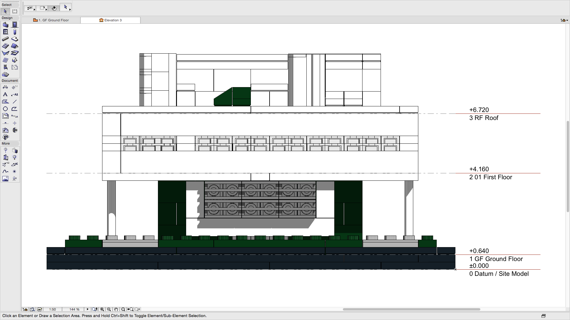
Image: Elevation view 3 (click to enlarge)
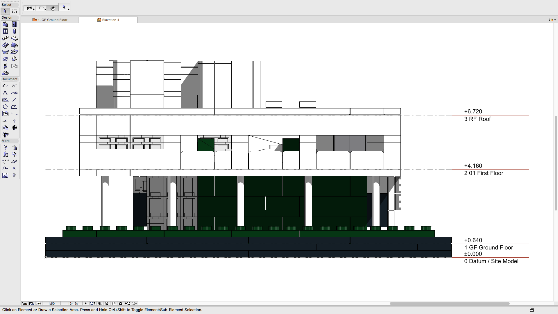
Image: Elevation view 4 (click to enlarge)
Sections
A section is similar to an Elevation except that it cuts through the model. This allows further internal elevations to be revealed as well as showing more detail about how the model is built.
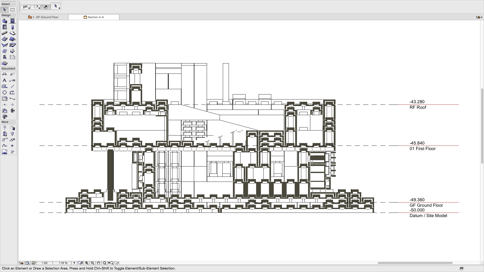
Image: Section view A-A (click to enlarge)
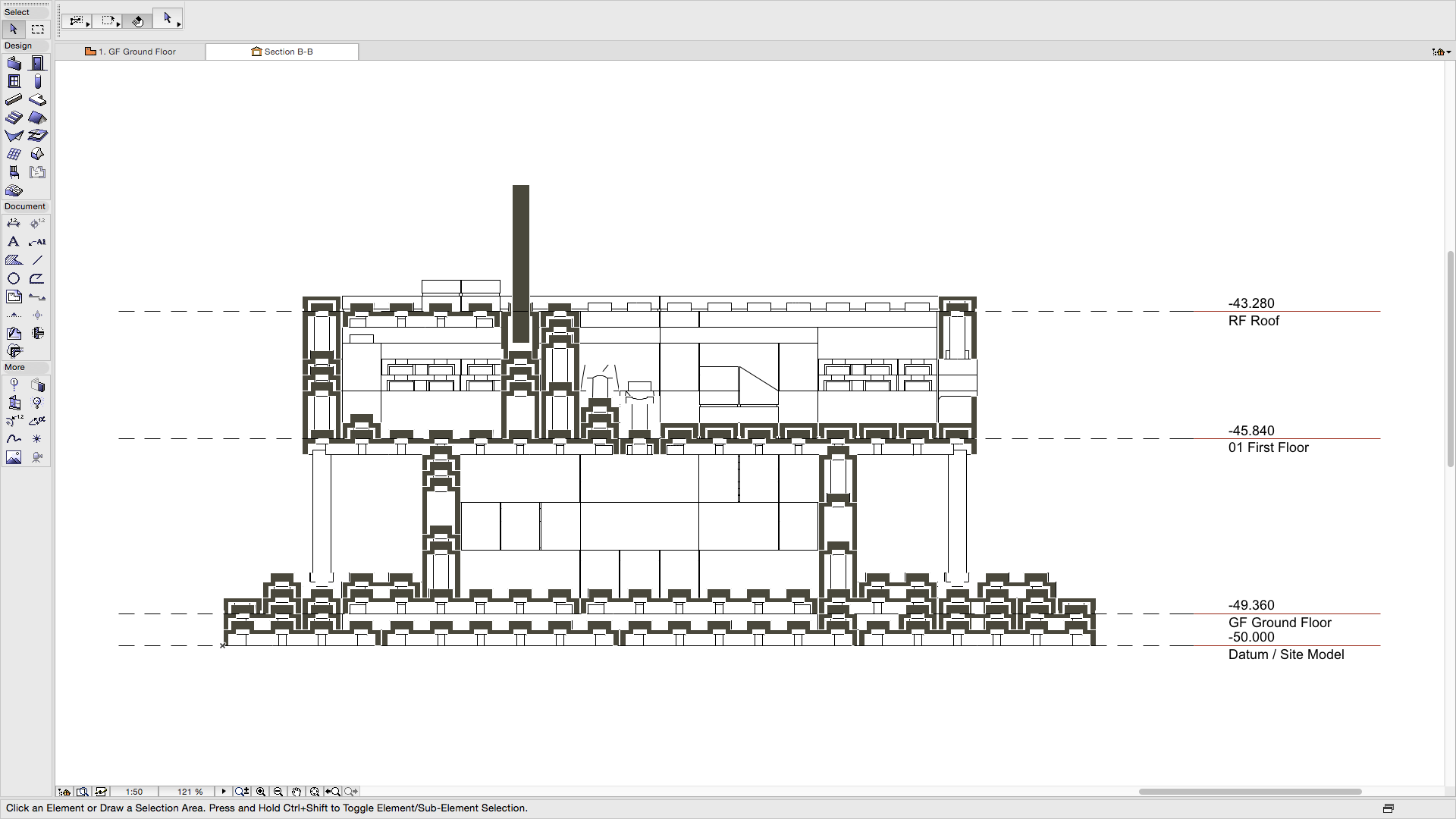
Image: Section view B-B (click to enlarge)
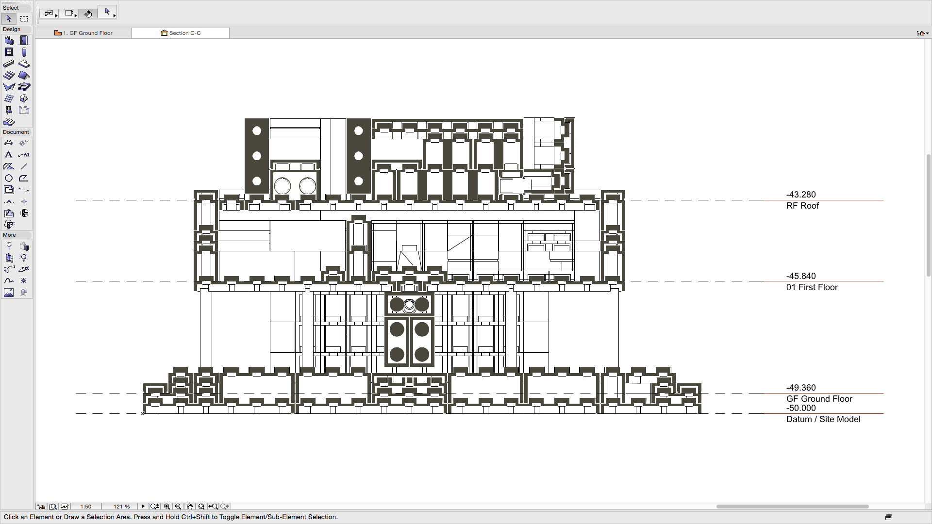
Image: Section view C-C (click to enlarge)
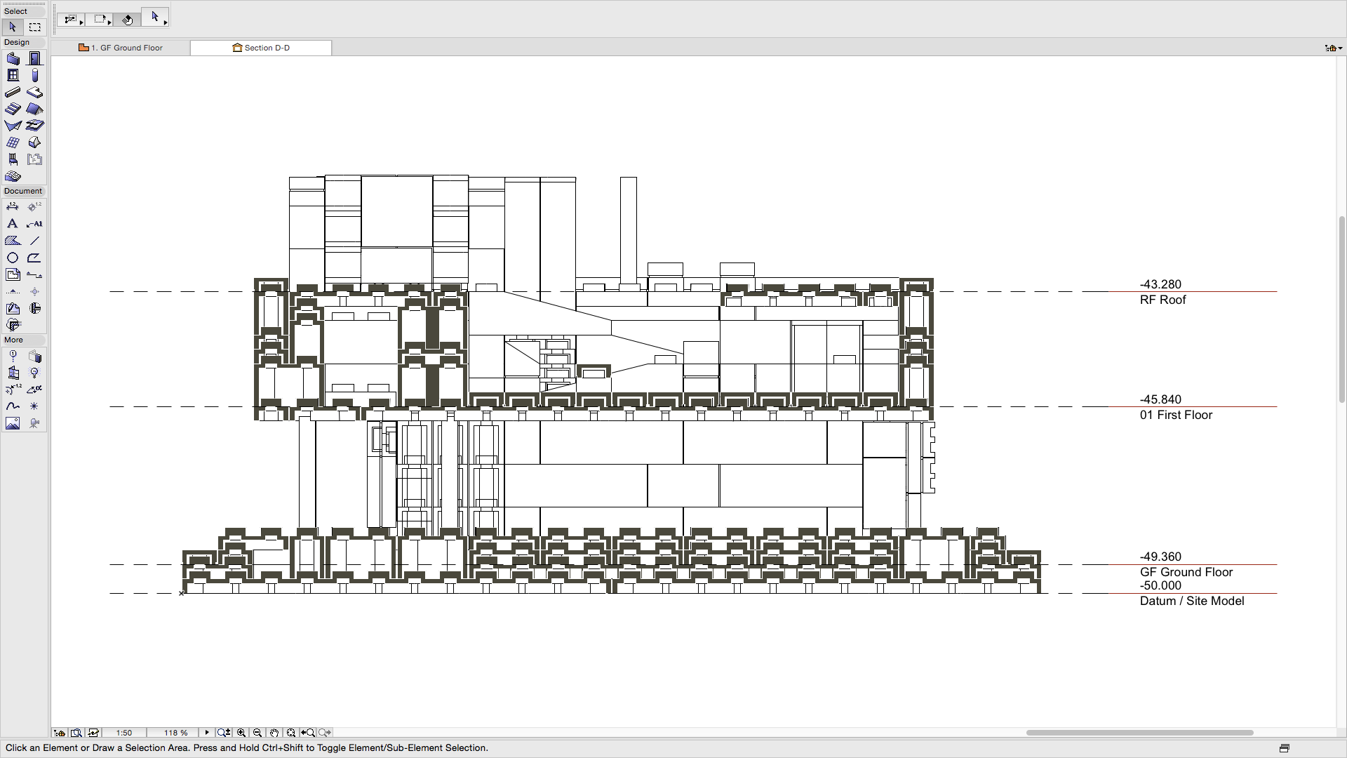
Image: Section view D-D (click to enlarge)
3D Views
Whilst traditional views can be created directly from the model, the model itself can be used to create different views. Often model authors focus on creating a model to produce the traditional outputs that are required by those receiving the information (i.e. plans, elevations and sections). However these authors forget that views of the model are often more useful in terms of conveying information. These 3D views can be put directly onto drawing sheets and can help to convey information clearly to others. Obviously these views are not possible with a traditional 2D approach.
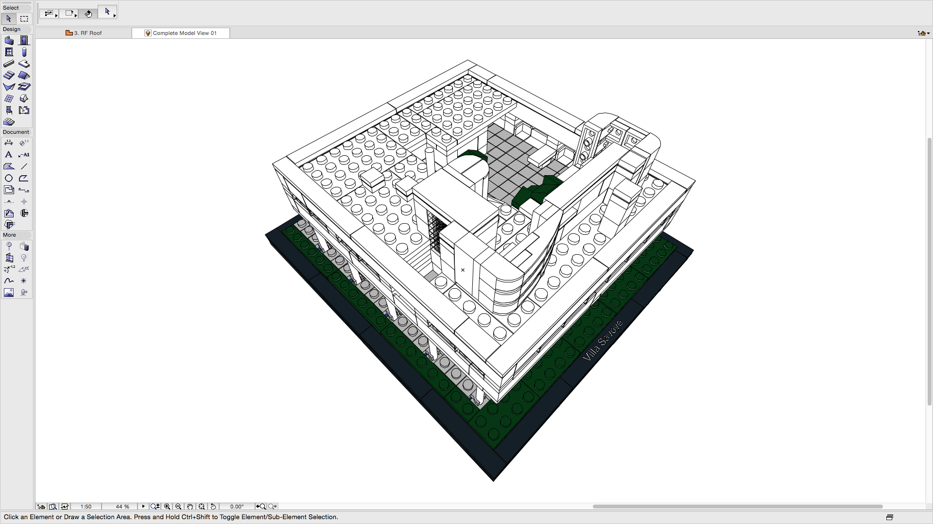
Image: 3D view 1 (click to enlarge)
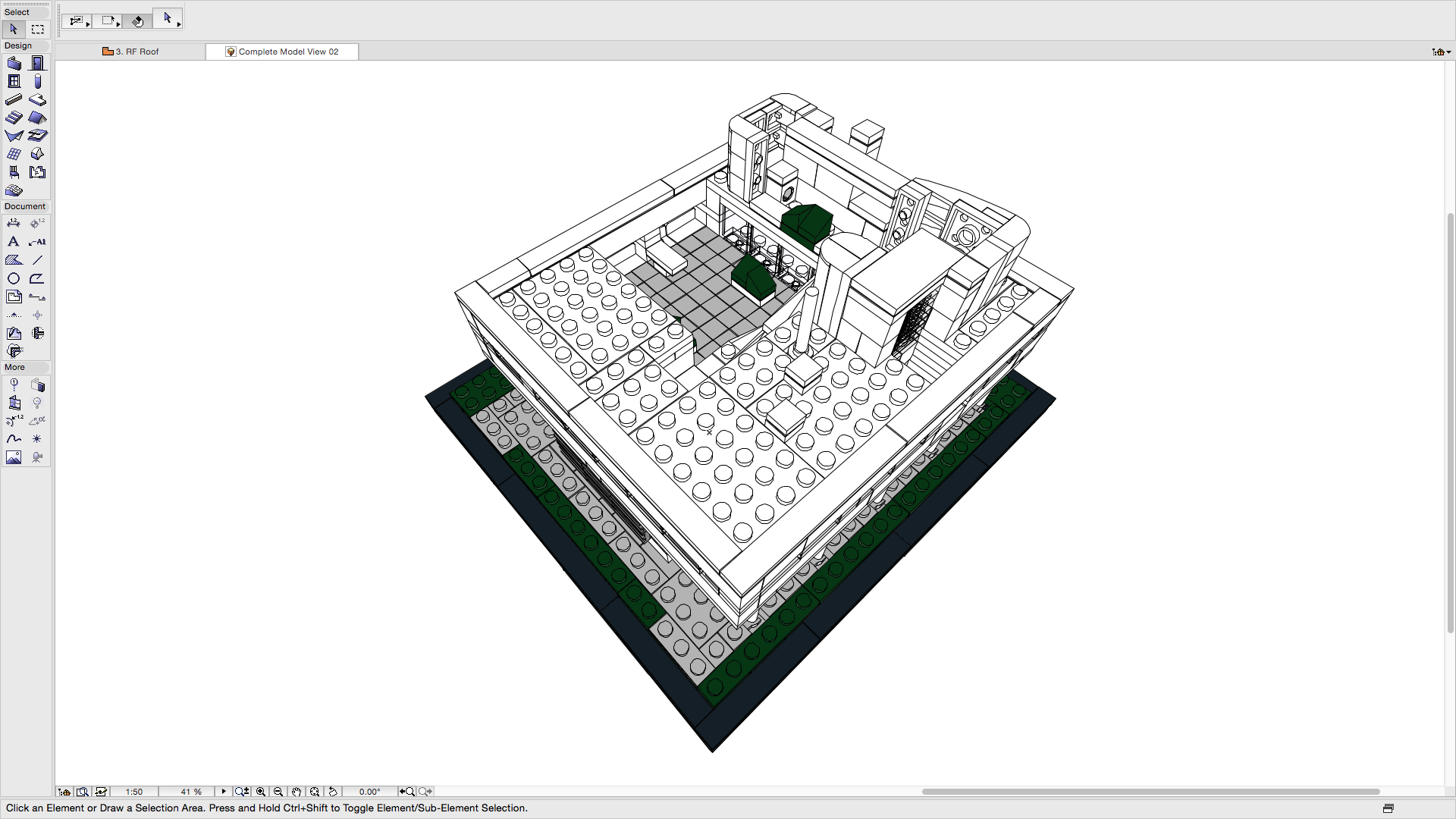
Image: 3D view 2 (click to enlarge)
The model can be displayed as a whole, as above, or limited to particular information. In this case the views below show specific selections of Components/Elements.
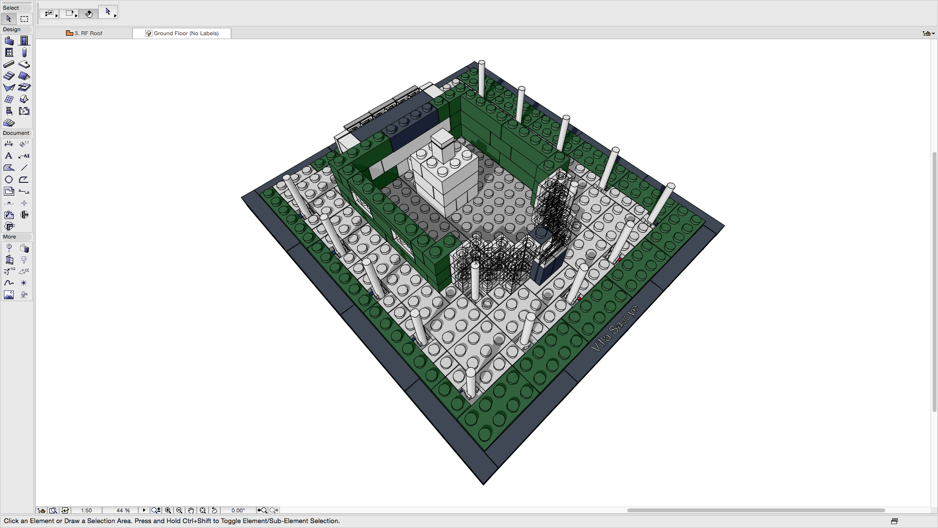
Image: 3D view of Site and Ground Floor levels (click to enlarge)
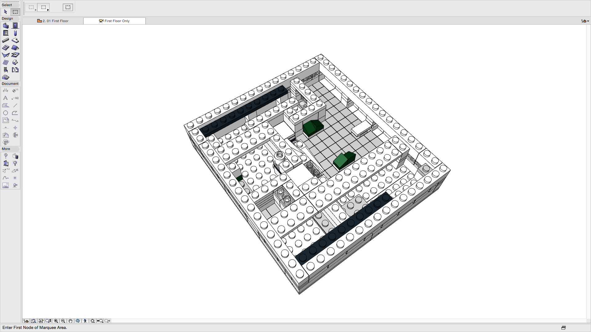
Image: 3D view of First Floor level (click to enlarge)
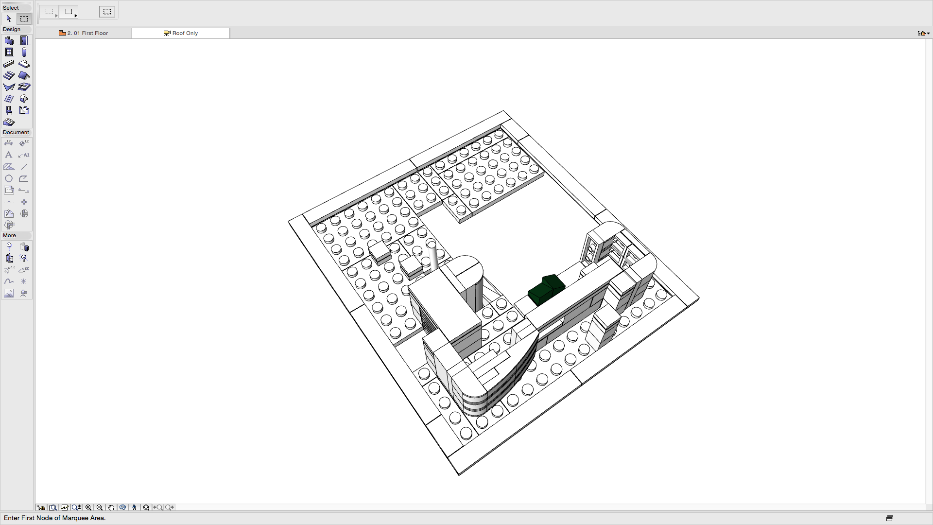
Image: 3D view of Roof level (click to enlarge)
Sliced 3D Views
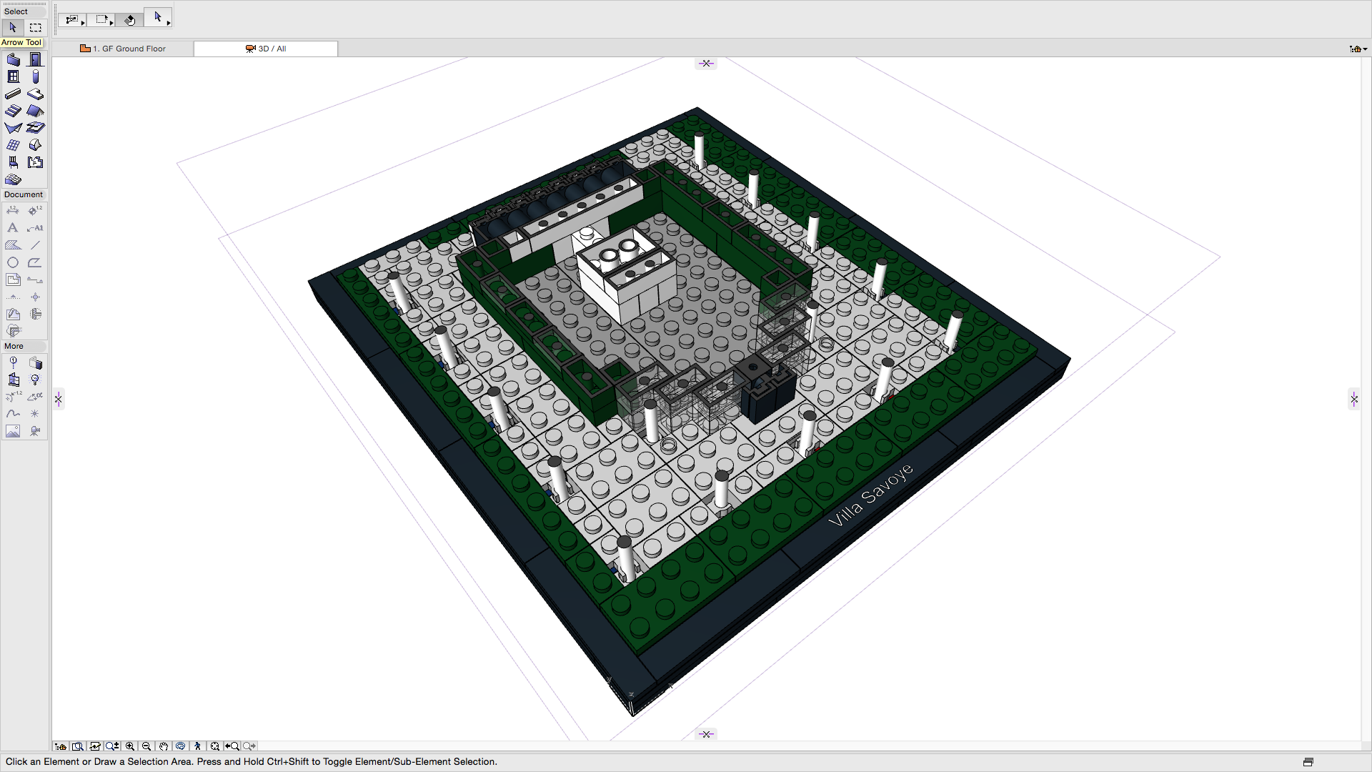
Image: 3D view cut horizontally (click to enlarge)
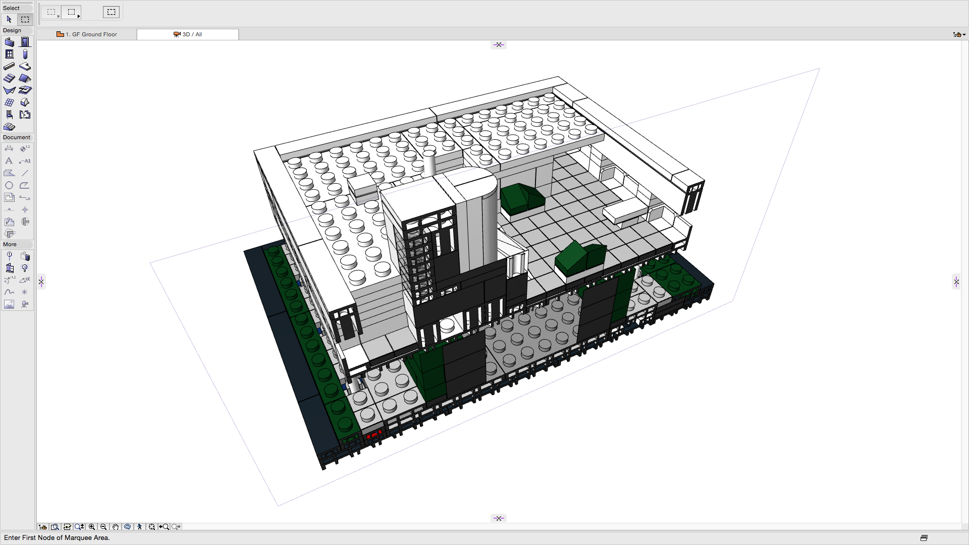
Image: 3D view cut vertically (click to enlarge)
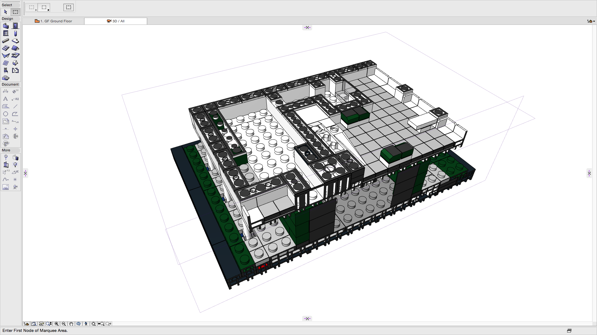
Image: 3D view cut horizontally and vertically (click to enlarge)
Note: Graphisoft ARCHICAD can also create Interior Elevations and Details. These have been excluded for this particular project.
Conclusion
Views allow authors to manipulate the model in order to create the final output. This means if any Component/Element is moved in any view the other views in which they appear will automatically be updated. This is a major benefit over a traditional 2D approach which would mean each view being updated individually. This in the past could have also have been carried out by different authors. This traditional approach can lead to errors between each view and introduces risk to the process. This can then have an impact on time and cost when the ‘building’ is constructed from this information.
In this case the errors would be fairly easy to spot but the larger and more complex the project the more costly these errors can become. Using a 3D model to produce consistent views is really the first obvious benefit of a modelling approach.
Rob Jackson, Associate Director, Bond Bryan Digital
![]()
Terms and conditions
All content provided on this blog is for informational purposes only. The owner of this blog makes no representations as to the accuracy or completeness of any information on this site or found by following any link on this site. Bond Bryan will not be liable for any errors or omissions in this information nor for the availability of this information. Bond Bryan will not be liable for any losses, injuries, or damages from the display or use of this information.
We are happy for others to share our blog pieces through all social media platforms. You may include links to the original blog pieces and use part of the blog to then provide a link to the original content. However we would appreciate it if the content is not reproduced in full on other sites or publications without written consent being granted by Bond Bryan.
This policy is subject to change at any time.
LEGO and the Lego logo are trademarks of the LEGO Group. Any trademarks, service marks, product names, corporate names or named features are assumed to be the property of their respective owners, and are used only for reference, without intent to infringe.