


LEGO Architecture meets BIM – Part 14: Manipulating model geometry in viewing tools
Introduction
A building information model (BIM) is a model that is built with a defined structure. This structure means that tools can use this structure to allow users to manipulate geometry in a number of different ways. For example building models will have an agreed set of Floors (also called Building Stories in IFC) and these horizontal planes provide a natural break point in the model. Of course lay people are already familiar with this concept when navigating a real building so being able to see each floor is a useful exercise.
As we have seen in previous posts we could split a model into a series of models or use the data structure to isolate specific parts of the model/building. One methodology I came across recently was a free IFC viewer called BIM Vision (which came about through a discussion about another upcoming blog piece!) which used another method to separate a model. This is based on a simple set of sliders which allow the viewer to manipulate the geometry. Below we have set out how this functionality allows us to view the ‘LEGO Architecture meets BIM’ project in a number of different ways.
Manipulation of geometry
So below we have set out some of the manipulation of the LEGO model that can be achieved with sliders. BIM Vision uses a ‘Storey Slide’ under the View menu. The sliders can be returned to their default setting by hitting the ‘Reset’ button to the right of the sliders.
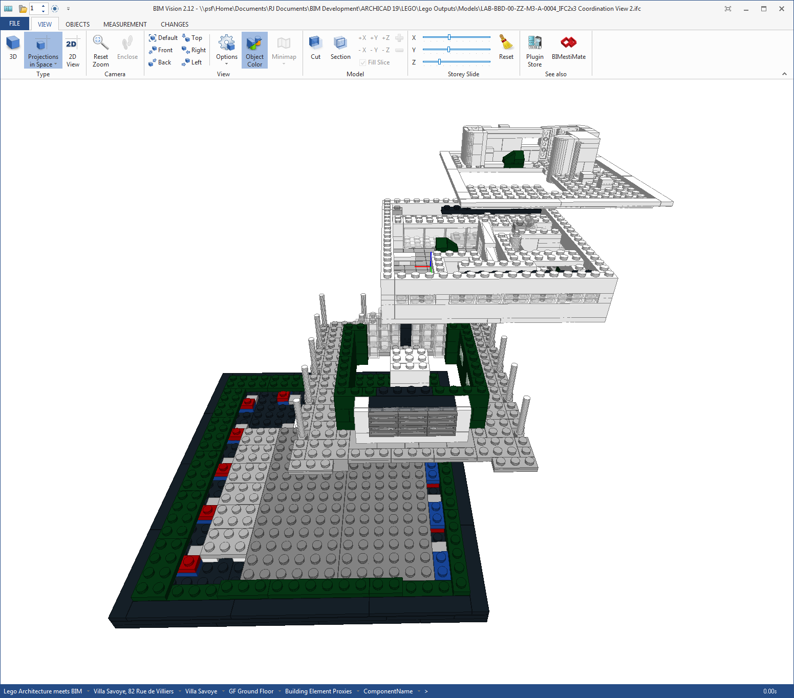
Firstly we can split the model vertically by adjusting the Z slider. This means we can quickly view each floor in isolation.
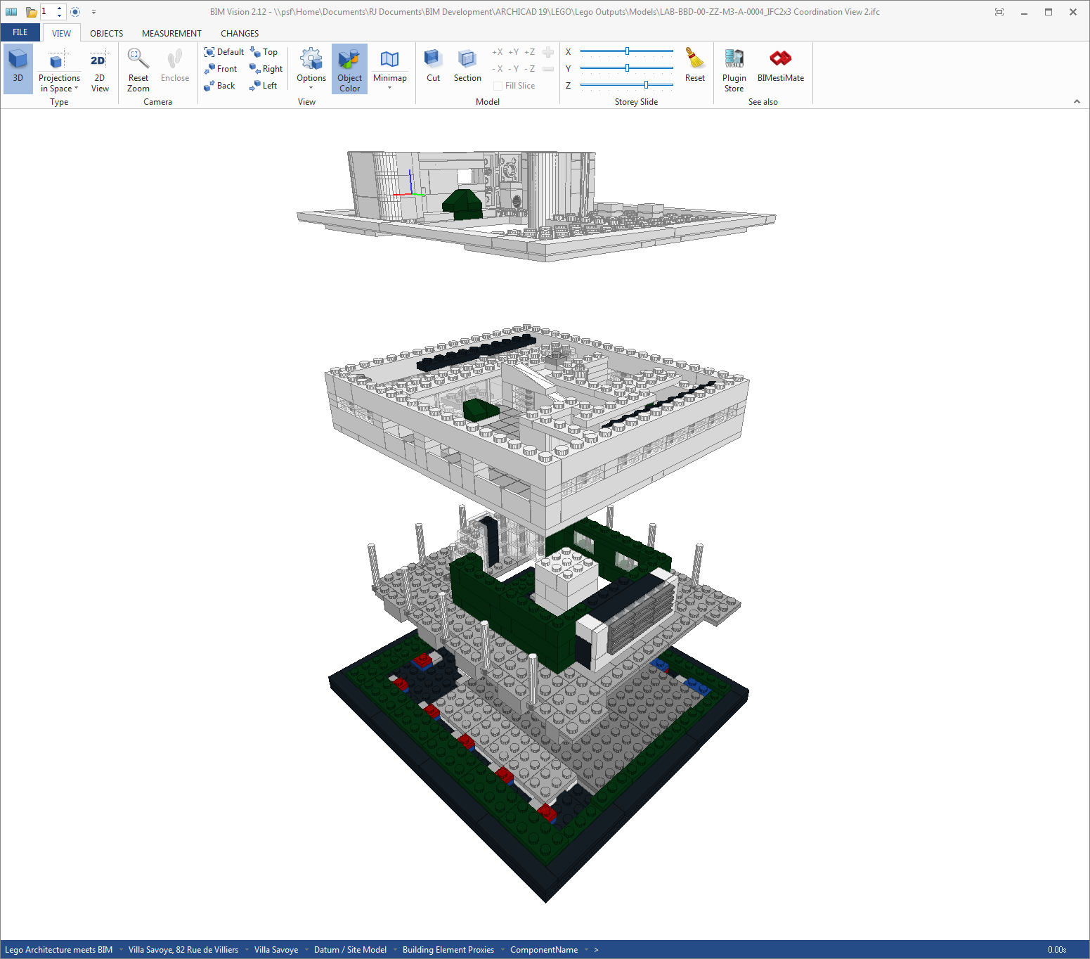
Image: Vertical (Z) slider (click to enlarge)
As well as vertically the sliders can be adjusted to move the elements horizontally. This can be done in either the X or Y axis.
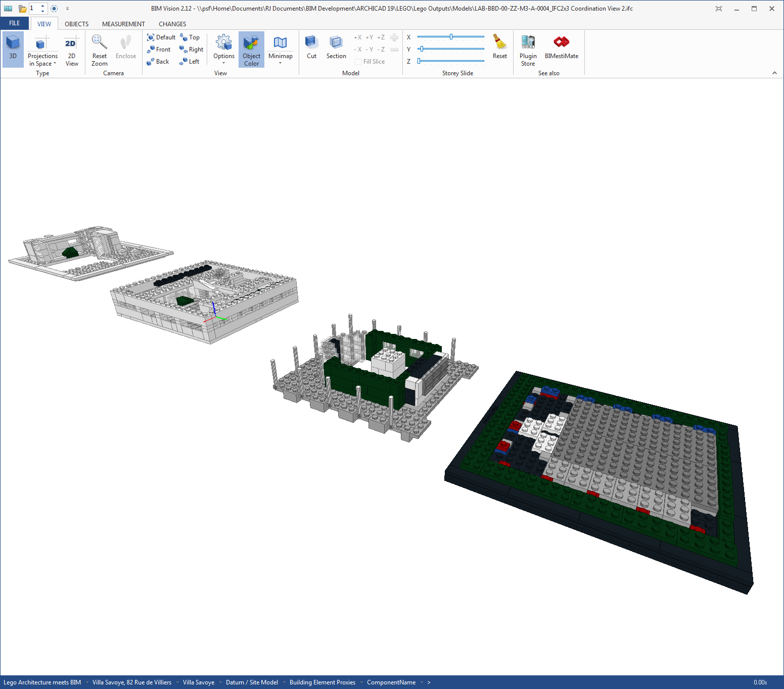
Image: Horizontal (Y) slider (click to enlarge)
If we pull the slider all the way to the end, the geometry moves so that all the floors are sat next to each other in the same vertical plane.
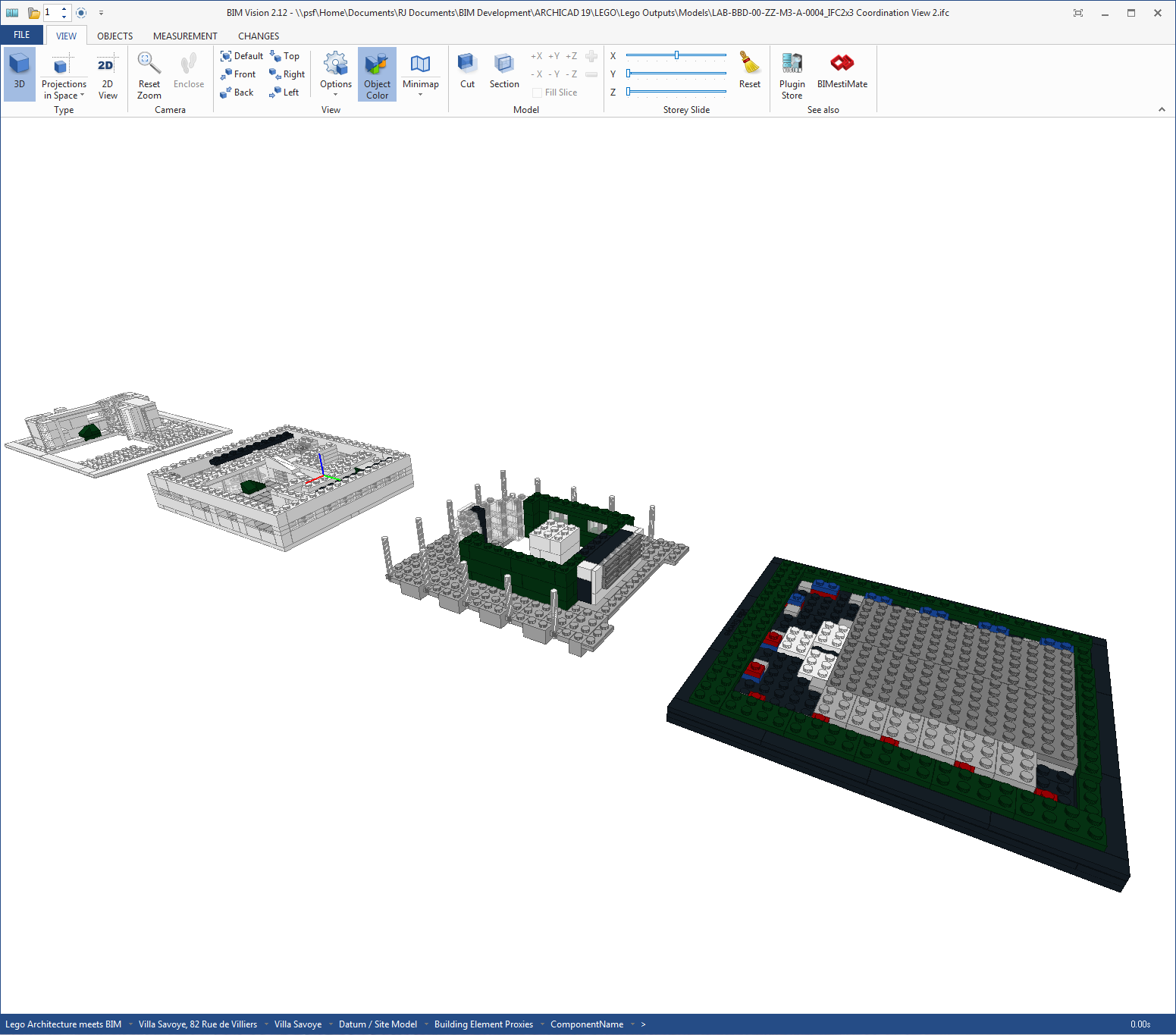
Image: Horizontal (Y) slider to furthest point (click to enlarge)
As well as pulling the model in a horizontal direction we can pull the model in combination.
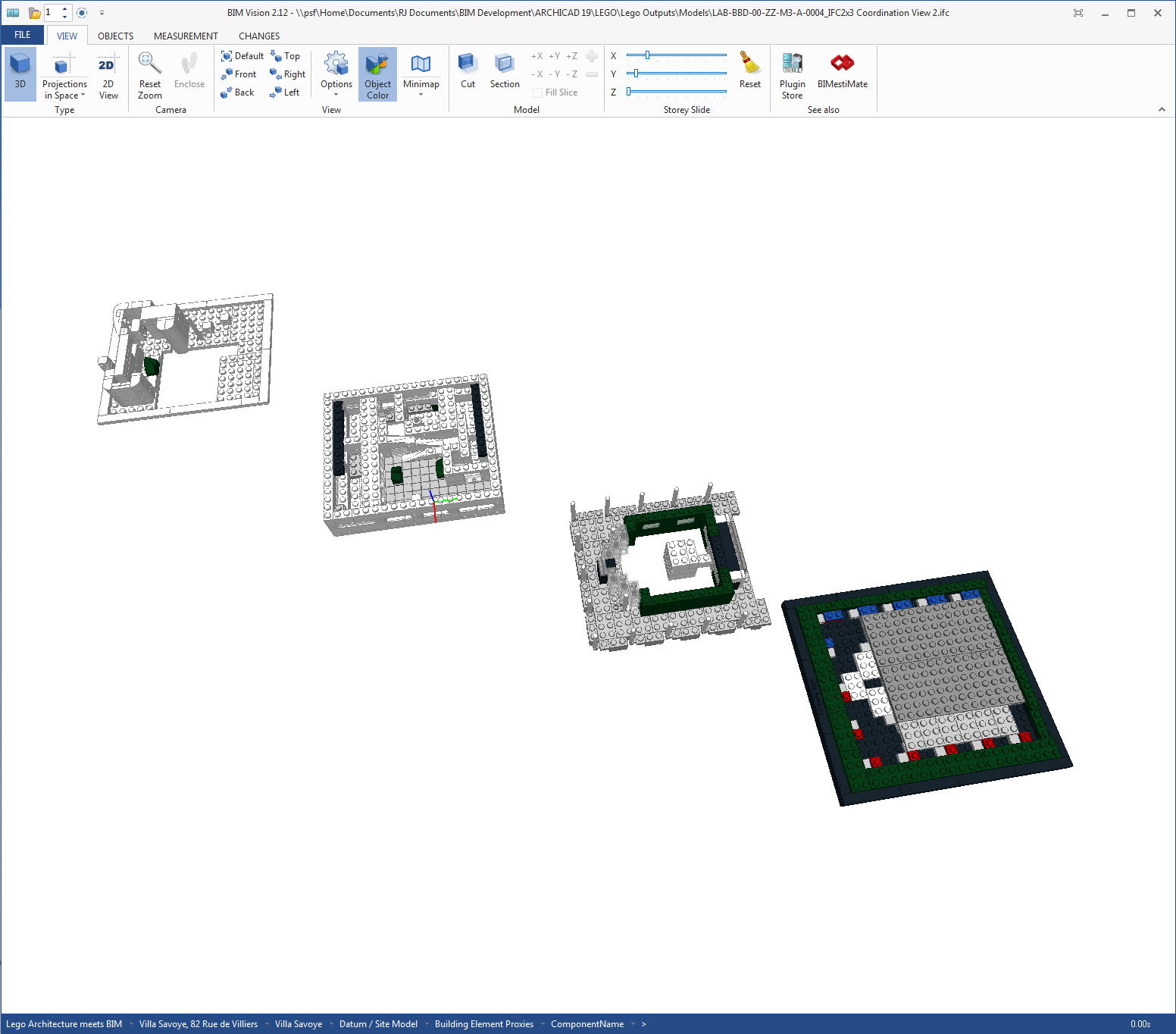
Image: Combination of horizontal sliders (X and Y) (click to enlarge)
Finally we can pull the model in both the horizontal and vertical planes.
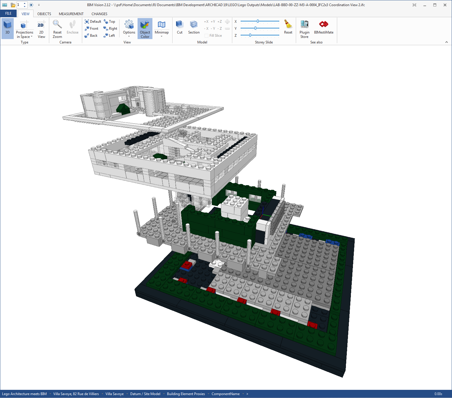
Image: Combination of vertical (Z) and horizontal sliders (X and Y) (click to enlarge)
Another view of the model pulled vertically and horizontally.
Image: Another view of the combination of vertical (Z) and horizontal sliders (X and Y) (click to enlarge)
As well as pulling the sliders we can use these in combination with other features. Below the sliders are used in combination with the ‘Cut’ functionality available in BIM Vision.
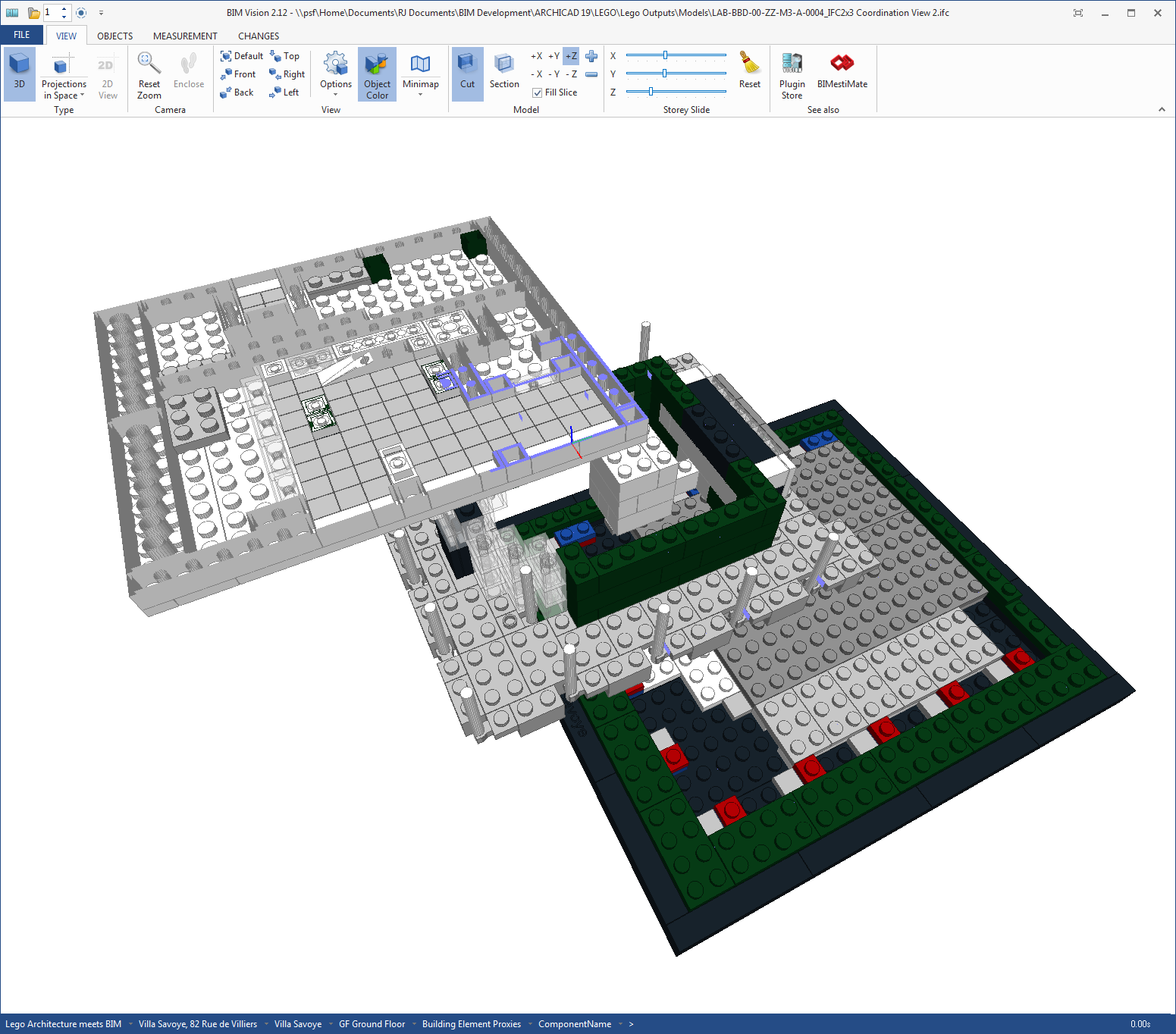
Image: Combination of vertical (Z) and horizontal sliders (X and Y) with Section cut (click to enlarge)
Of course BIM Vision isn’t the only tool with sliders and as we saw in a previous post in this series, Autodesk A360 also has the ability to use sliders to ‘explode’ a model.
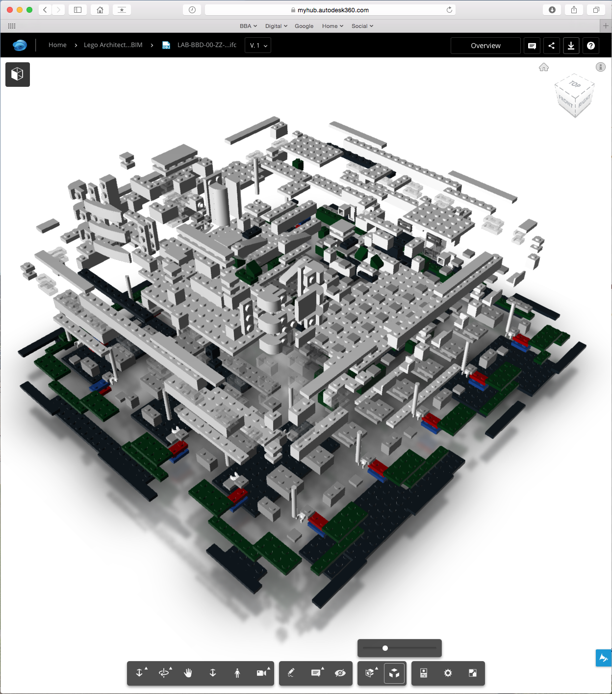
Image: Explode slider in Autodesk A360 (click to enlarge)
Conclusion
The BIM Vision model viewer is unfortunately only available on PC but the functionality demonstrates how a well structured model can be beneficial to the recipient. It would be nice if more model viewers incorporated this functionality as its implementation is very elegant and even technophobes will be able to understand how this works with a minimal amount of training.
The A360 functionality is a little less easy to understand how it would be beneficial to a real project, although it is nice to play with. But its simplicity of use is the same as BIM Vision and this kind of simple functionality is key to ultimately help everyone adopt BIM, from designers through to end users.
There are probably many tools out there with similar functionality and the aim was not to cover every possible approach but more to highlight this type of functionality exists.
Combining a structured model with an open data format means the model can be shared with others to understand and use for their needs. The need to focus on getting both geometry and data out of authoring tools will allow more tools to be used by those who are not authoring models. The need to improve viewing tools with simple easy to understand functionality for non-model authors is paramount if the industry ultimately hopes to move away from paper based exchange. I’m off to ask other software companies to include more of this kind of functionality…
Rob Jackson, Associate Director, Bond Bryan Digital
![]()
Terms and conditions
All content provided on this BIM Blog is for informational purposes only. The owner of this blog makes no representations as to the accuracy or completeness of any information on this site or found by following any link on this site. Bond Bryan will not be liable for any errors or omissions in this information nor for the availability of this information. Bond Bryan will not be liable for any losses, injuries, or damages from the display or use of this information.
We are happy for others to share our blog pieces through all social media platforms. You may include links to the original blog pieces and use part of the blog to then provide a link to the original content. However we would appreciate it if the content is not reproduced in full on other sites or publications without written consent being granted by Bond Bryan.
This policy is subject to change at any time.
LEGO and the Lego logo are trademarks of the LEGO Group. Any trademarks, service marks, product names, corporate names or named features are assumed to be the property of their respective owners, and are used only for reference, without intent to infringe.